Managing the Carrier Ethernet Service Lifecycle
Discover how to manage the Carrier Ethernet service lifecycle effectively.
Overview
Carrier Ethernet Solutions: Setup, Monitoring, Fault Management, Repairs
Ensure profitable Ethernet service delivery by streamlining the deployment, monitoring, and maintenance of your carrier ethernet network.
This practical guide from RAD, a leader in Carrier Edge solutions specializes in Carrier Ethernet demarcation, describes the various test procedures, along with implementation considerations and recommendations for use at turn-up, ongoing monitoring, and other critical points throughout the service lifecycle to ensure quality of service and maintain Ethernet CoS.
What’s in the white paper:
- Service Validation Tests
- Service Turn-Up
- On-going Service Control and Monitoring
- Fault Management and Recovery
- RAD’s Testing-Enabled Ethernet Demarcation Devices
1. Introduction
As Carrier Ethernet services become mainstream for business, wholesale and mobile backhaul applications, carriers and service providers place greater focus on shortening deployment times, increasing operational efficiency and minimizing TCO (total cost of ownership) to ensure profitable service delivery. As a result, providers require a comprehensive set of tools to help them provision, monitor and control E-Line, E-Tree and E-LAN services more effectively. Beyond the ability to optimize network operations and meet customer service expectations, such tools provide substantial cost reductions and revenue gains:
- Accelerate time to market by reducing time and effort required for new service rollouts
- Cut down truck-rolls, on-site technician calls and Trouble Tickets with remote testing, end-to-end visibility and proactive monitoring
- Minimize penalties associated with SLA (service level agreement) breaches
- Reduce customer churn with clear service performance reporting and fewer billing disputes
Drawing on RAD’s extensive experience in helping carriers maximize Carrier Ethernet benefits, the following paper describes the various test procedures that are used at critical points throughout a service lifecycle, together with implementation considerations and practical recommendations.

2. Service Validation Tests
Quite a few test procedures – both standard and non-standard – are available to carriers and network operators for monitoring network health and managing service-affecting faults. Ethernet OAM (operation, administration and maintenance) functions as well as other tools can be performed via dedicated probes connected to the carrier’s network equipment at different service sites. Ideally, however, the tests are performed directly by demarcation devices at the service handoff points, provided that these devices are equipped to handle such tests effectively.
Below is an overview of the different test tools in use today.
2.1 IEEE 802.3-2005 (formerly 802.3ah)
Ethernet Link OAM is part of the IEEE (Institute of Electrical and Electronics Engineers) set of standards. It relates to a single Ethernet link, typically the access connection between the customer premises and the network edge. Specific link monitoring procedures include auto-discovery, heartbeat, and fault notification messages; link statistics; MIB variable retrieval; and remote loopbacks.
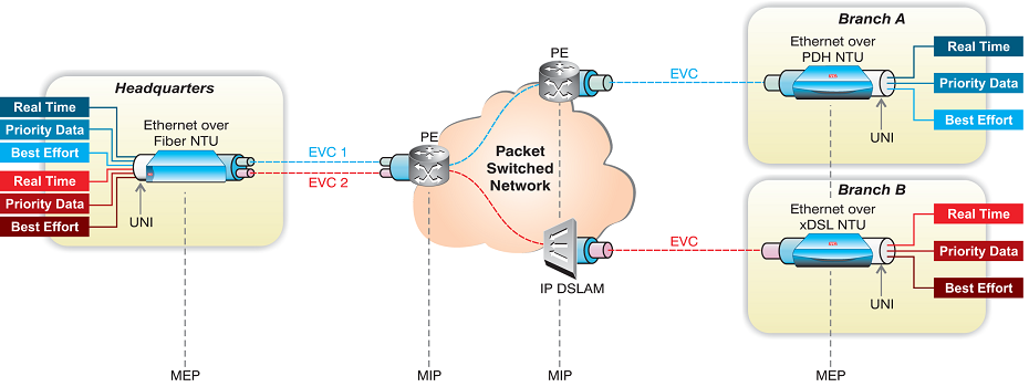
2.2 IEEE 802.1ag
Ethernet Service OAM, also termed Connectivity Fault Management (CFM), enables Ethernet service monitoring over any path, whether a single link or end-to-end, allowing the service provider to manage each Ethernet virtual connection (EVC) separately regardless of the underlying transport layer. CFM partitions a network into maintenance domains and hierarchy levels that are allocated between users, service providers and third-party operators. It assigns maintenance end points, or MEPs, to the edges of each domain and maintenance intermediate points, or MIPs, to ports within domains. This helps define the relationships between all entities from a maintenance perspective and permits each entity to monitor the layers under its responsibility to easily localize problems. Service monitoring use several functions including continuity check, link trace and loopback.
The figure below illustrates the various maintenance points in an EVPL service involving a single maintenance domain with one level:
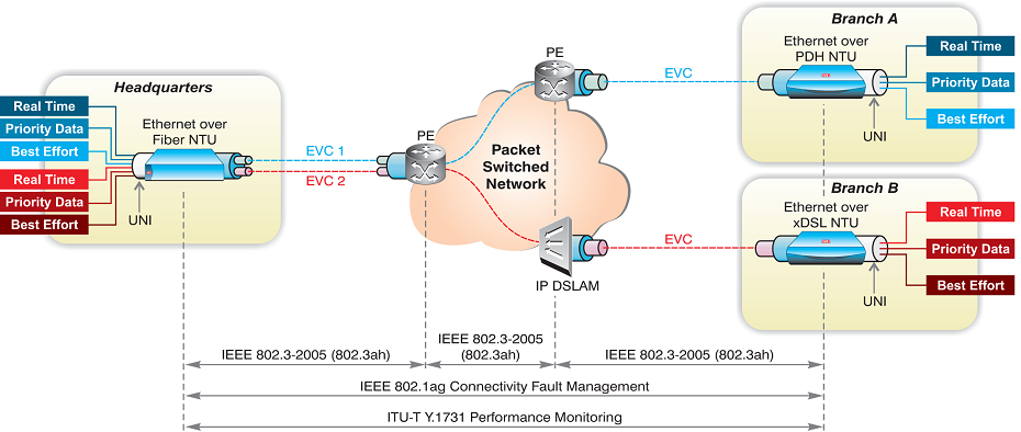
2.3 ITU-T Y.1731
The “OAM Functions and Mechanisms for Ethernet-based Networks” standard by the International Telecommunication Union (ITU) is used for Ethernet service performance monitoring (PM), enabling the service provider to measure frame delay, delay variation and frame loss SLA parameters. It also includes fault management functionalities similar to CFM’s, such as continuity check, loopbacks and link trace, with the addition of alarm indication signal (AIS) and remote defect indication (RDI) messages.
The following figure displays the various network sections to which different OAM procedures apply:
2.4 RFC-2544
The Internet Engineering Task Force (IETF) standard RFC-2544, Benchmarking Methodology for Network-Interconnect Devices, defines testing procedures for evaluating the performance of network devices, among which are network throughput measurements. These allow the service provider to baseline service performance and determine the available bandwidth for each EVC, by establishing the maximum transmission rate at which no packets are dropped. In addition to throughput testing, RFC-2544 includes frame loss and frame latency tests.
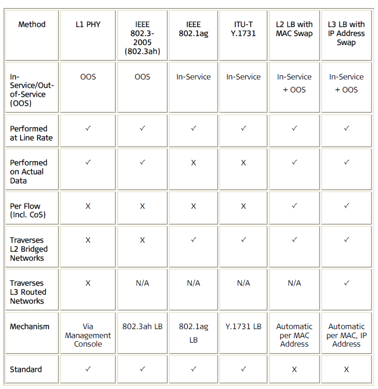
2.5 Diagnostic Loopbacks
Loopback messages between service points are important tools in the process of detecting and repairing connectivity problems. Today operators have a large variety of disruptive (out-of-service) and non-disruptive (in-service) loopback test procedures at their disposal, to help them address faults at various layers. The following table summarizes the various loopback methodologies and their main capabilities:
3. Service Turn-Up
Controlled introduction of a new service typically includes such steps as service setup, in-field testing to validate link and service connectivity, and acceptance tests to verify that the service is running smoothly according to the SLA and the QoS (quality of service) and CoS (classes of service) it defines. Testing at this point also serves for generating a baseline for performance parameters, to which future test results will be compared. Specifically, KPI (key performance indicators) metrics are established for end-to-end throughput, packet delivery ratio, latency, and jitter. These results are recorded as the service “birth certificate” and are archived for customer reporting, SLA comparison and future use as needed, for example, to evaluate performance after upgrade or repairs. To accurately establish service behavior over time, burn-in tests are performed for 24-72 hours before the link is cleared for critical applications.
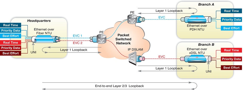
Let us consider, for example, a 3-CoS EVPL (Ethernet Virtual Private Line) service between several locations: Enterprise headquarters, remote branches and a data center. Some of these locations reside outside of the provider’s service footprint and therefore the service path includes segments that traverse another carrier’s network. The provider in this case must ensure that the EVC is operational and running fault-free, that each traffic type adheres to its respective SLA QoS guarantees, and that visibility is established throughout the entire service path, including across a third-party network, so that network operators can accurately pinpoint the origin of problems and ensure a speedy resolution.
The following table summarizes the various functions that are typically associated with service turn-up and the different tools network operators use to perform them:
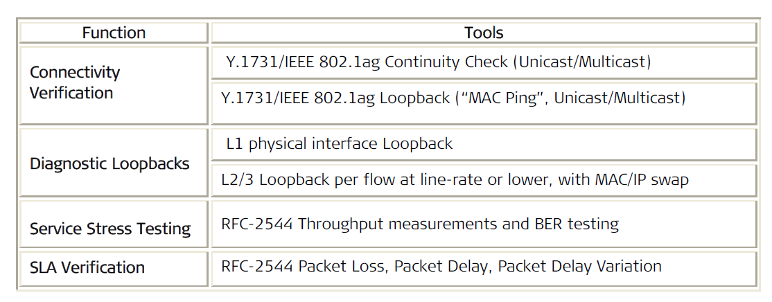
Further details on selected procedures are provided in the sections below:
3.1 Connectivity Verification
Before initiating any tests involving high traffic volumes, it is imperative to verify that the service connections are up and configured properly. Service connectivity is typically verified using 802.1ag/Y.1731 continuity check (CC) messages to test the end-to-end path, whether this path traverses a single or multiple networks.
While other tools may also be used to check that connections are established, the value of CC heartbeat messages is in helping service operators validate that peer elements are defined correctly. This allows quick identification of mismatch errors in MEP configuration – errors which may result in duplicate IDs and service cross-connects between different customers or maintenance domains.
During turn-up connectivity testing, the demarcation device installed at headquarters can be configured to send periodic CC messages to the other units installed at the remote locations and to check for incoming CC messages sent at that period. For each maintenance domain level, i.e., service provider, third-party carrier and enterprise customer, the MEPs are identified by their respective MEP IP, MD (maintenance domain) and MA (maintenance association). Upon receipt of a CCM, the receiver checks the MEP and service IDs to ensure conformance. LOC is declared if no CC messages are received from remote MEPs within 3.5 times the transmission period. Further details on the next steps taken in such cases are provided in Chapter 5: Fault Management and Recovery.
3.2 Diagnostic Loopbacks
Ethernet circuit validation at the turn-up stage can be verified with on-demand diagnostic loopbacks. In this case, the demarcation device is configured to loop back tested traffic to the test originator – whether a management station, test head or a demarcation device at another location – at wire-speed. The demarcation device will also swap the MAC/IP source and destination addresses to ensure that the traffic correctly traverses the Layer 2 or Layer 3 network back to the source. This allows network operators to verify service path configuration and to test connection quality for actual traffic, for example by running diagnostic loopbacks for all VLAN IDs mapped to a particular EVC. Other variations of such tests, including multi-flow and “always on” loopbacks, are described in Chapter 5: Fault Management and Recovery.
3.3 Stress Testing
RFC-2544 throughput measurements are used to establish the effective bandwidth rate the enterprise actually receives for each tested EVC by determining the maximum traffic load for which no errors occur. The test can be conducted bi-directionally or unidirectionally using a test head device or a demarcation device equipped with built-in RFC-2544 tester capabilities, thus eliminating the need for external testing equipment. The procedure outlines a set of frame sizes for which throughput measurements are conducted. This helps to pinpoint the processing delays caused by short frames and identify network equipment that is having trouble handling larger packets. Based on packet receive-rate results, the service provider can also determine the maximum packet length that can be offered to the enterprise with SLA guarantees, after calculating frame extension allowance for headers, SP-VLAN tags and other overhead.
As RFC-2544 procedures were originally designed for individual device testing in a lab environment and may be time consuming, performing several tests concurrently is advisable.
3.4 SLA Verification
RFC-2544 procedures can also be used to determine network performance and to verify that it is in-line with the KPIs guaranteed in the enterprise SLA. Packet loss is measured by comparing the number of transmitted and received frames at various network loads and frame sizes, then calculating the percentage of dropped frames. Average round-trip or one-way latency is determined by analyzing time stamps on tested frames. Packet jitter, or delay variations over time, is also part of the test procedure although, technically, it is not included in the official RFC-2544 standard.
A new standard, ITU-T Y.1564 (formerly Y.156sam), has been recently approved to provide a better fit for SLA validation during Carrier Ethernet service activation. It allows efficient measurement of CIR and EIR bandwidth, latency, jitter, and frame loss in a single procedure, using uni- or bi-directional loopbacks between a Y.1564-enabled test unit operating opposite another test unit or opposite a demarcation device with wire-speed support.
4 On-going Service Control and Monitoring
KPI measurements are also performed on an on-going basis, to monitor network health and ensure that QoS is maintained per class of service and in accordance with the contracted SLA. Continuous monitoring is required to detect service degradation and network congestion, prompting relevant alerts and advising when an increase in bandwidth is required. When service outages or connectivity faults are identified, Trouble Tickets are initiated and appropriate remedial actions taken.
The collected data is integrated with billing and other back office systems, while reports of network and service conditions may be available to the enterprise periodically and on-demand. OAM tests are performed at a frequency that balances between the need to quickly detect and repair problems, and the service provider’s desire to limit the toll such tests take on network and bandwidth resources.
The table below provides a summary of on-going monitoring tools and functions:
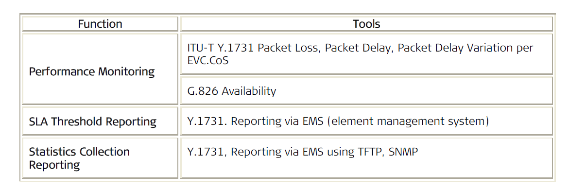
4.1 Performance monitoring
Frame Delay (latency): Tests a frame’s travel time across the network end-to-end, i.e., between ingress UNI-N (network side of the UNI) and egress UNI-N. Frame size, transport media, congestion, and the network elements themselves are all contributing factors to network latency. The test measures the elapsed time between the start of transmission of the first bit of a time-stamped delay measurement (DM) frame at a source MEP (e.g. ETX-A at headquarters), and the arrival of the last bit of that same frame at the destination (e.g. RICi at branch A). The receiving MEP then compares the time-stamp to its own reference clock and calculates end-to-end transmission delay. Unidirectional delay measurements require that both MEPs are synchronized. Alternatively, frame delay can be measured on a round-trip basis, by analyzing the difference between the transmit time stamp in a DM message and the receive time stamp of the DM reply that was returned to the originating MEP.
Frame Delay Variation (jitter): Measures the variation in frame delay by comparing the time interval between consecutive frames belonging to the same CoS flow at the ingress UNI to the delay in arrival of the same frames at the egress UNI. In round-trip delay variation calculations, FDV is defined as the difference between two consecutive frame delay measurements at the same MEP.
Frame Loss: Measures the rate of frames that are being dropped during transmission. Uni-directional (dual-ended) frame loss ratio can be determined using live traffic, by analyzing the counters for sent and received frames at the service end points and measuring the number of lost/discarded frames out of all frames that should have been delivered within a specified time interval. Bi-directional (single-ended) frame loss ratio measurements refer only to the initiating device and involve the exchange of loss measurement (LM) messages and LM replies.
Availability: Calculates service uptime based on the number of seconds that the network or service were unavailable to the enterprise. For example, with an SLA guarantee of Four Nines (99.99%) availability, the enterprise should not experience service down-time for more than 4 minutes and 19 seconds throughout a 30-day month [60 minutes x 24 hours x 30 days x (1-0.9999) unavailability threshold], excluding scheduled maintenance windows. The demarcation devices determine the service availability rate by applying a G.826-based calculation on frame loss ratio (FLR) levels or by leveraging on-going CC measurements.
The demarcation devices record minimum, maximum and average values for delay and delay variation, together with the rate of frame loss and the number of seconds during which the service was unavailable – all for a pre-set interval. Performance statistics are collected and sent periodically to the service provider’s network management system (NMS) to deliver an up-to-date account of service quality, as well as an historical view of network and service behavior, without over-taxing the network with excessive management traffic. This enables both provider and customer to easily evaluate actual performance over time and compare it to SLA guarantees.
4.2 SLA Threshold Reporting
Advanced demarcation devices support user-defined threshold configuration, whereby users can define thresholds according to SLA objectives and receive exception traps and alarms. Device- and event-based threshold configuration enables proactive notification of SLA violations at the device level without the need to rely on external performance monitoring software.
5 Fault Management and Recovery
An important element of service lifecycle management is the ability to identify, locate and notify service-affecting problems by various network elements, most importantly by the demarcation devices at the service hand-off points. Fault detection and isolation, together with remote test and repair functionalities, are crucial for containing and correcting problems before they escalate. When a service outage is reported, a suite of tests is performed to remotely localize the fault prior to a technician dispatch. This reduces MTTR (mean time to repair) and minimizes the effect on users, while lowering operating expenses by eliminating unnecessary (and expensive) truck rolls and ensuring that technicians are sent to the right location.
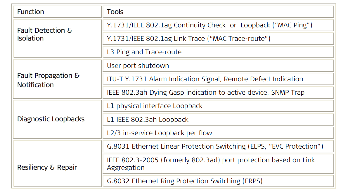
5.1 Fault Detection, Isolation and Notification
Periodic 802.1ag/Y.1731 CC frames are sent at pre-set intervals to check the status of link and service connectivity for preventive maintenance. When loss of continuity occurs, the originating MEP activates the RDI flag in the next CC message to indicate connectivity problem, notifies the user and sends an alarm to the NMS. This procedure can also be used to initiate an uplink connection switchover. The specific failure point can be located by sending a link trace request for hop-by-hop path tracking, to identify non-responsive MIPs. The link trace test results display the responsive nodes, thus enabling operators to map the service path and dispatch a technician to the right location for a quick repair. Alternatively, the operator can use the 802.1ag loopback test to isolate the problem, by looping successive intermediary points in the path until the fault is identified. In addition to the RDI and AIS fault notification tools, the demarcation device can automatically shut down user ports when error conditions on the network end are detected. This alerts customer equipment on both ends of the link that an alternative route is required.
5.2 Diagnostic Loopbacks
Remote diagnostic loopback tests can be performed in-service, to analyze service connectivity across EVCs without taking the customer link down or affecting untested traffic. For example, a customer service representative (CSR) working a Trouble Ticket relating to a specific EVC can generate an end-to-end flow loopback test between the demarcation devices at headquarters and branch B. The procedure is selective and executed per a variety of flow criteria, including VLAN ID, class of service (P-bit) and source or destination MAC or IP address. This allows the loopback messages to traverse multiple hops, including intermediary switches or bridges, without disrupting the traffic flows that are not being tested.
The receiving device swaps the source and destination MAC or IP addresses of incoming packets prior to looping them back, so as not to create a conflict in the switches or bridges along the path.
Where diagnostic loopbacks are performed according to selective criteria, network operators can allocate a small portion of EVC bandwidth for constant, “Always On” loopbacks, whereby Ethernet circuit validation is executed without the need for signaling the remote device. In addition to simplifying operations, this also eliminates interoperability issues between the demarcation device and Ethernet test sets.
Furthermore, as a single demarcation device supports multiple loopback flows simultaneously, both towards the user and the network, the number of test sets can be significantly reduced to allow multiple independent SLA monitoring instances per demarcation device. For example, the same demarcation device can be used by a wholesale provider, a retail provider or mobile operator and by the customer – each using a different loopback classification key.
5.3 Resiliency and Repair
Service resiliency and protection are critical for ensuring High Availability and speedy restoration in the event of network outages. Without proper redundancy for link and path protection, even brief failures may result in compromised QoE (quality of experience) for the user, due to retransmissions or even loss of service altogether.
The demarcation devices address these issues by providing various tools for ensuring resiliency of the access link, as well as the end-to-end connection. Examples of such tools include link aggregation group (LAG) using IEEE 802.3-2005 LACP (link aggregation control protocol), in which parallel links between a demarcation device and the neighboring PE (provider edge) are bundled to a single virtual link; Ethernet linear protection (G.8031) – also called “EVC protection” – which uses OAM continuity check messages to detect EVC failure and revert to a backup path. In addition, Ethernet Ring Protection Switching (G.8032 ERPS) uses ring topology to ensure traffic resiliency with fast switch-over mechanism.
6 RAD’s Testing-Enabled Ethernet Demarcation Devices
RAD’s intelligent Ethernet demarcation devices are equipped with advanced testing capabilities to lower TCO in Carrier Ethernet service deployments:
- CapEx Savings 1: Single-box solution for service delivery and testing eliminates the need for additional equipment and test sets, by providing probe functionality when working opposite test heads and performing test traffic generation when working opposite other NTUs
- CapEx Savings 2: Flow-based traffic management and testing improves cost-per-port and eliminates unexpected port availability issues during installation and turn-up
- Short Time-to-Revenues: Easy service upgrades with remote software updates
- OpEx Savings: Minimize unnecessary truck rolls with automated, remote monitoring, testing and reporting; Ensure productive on-site technician calls with fault localization
Needless to say, such functionalities can not be found in simple or even managed Ethernet media converters, nor are they supported by standard Ethernet switches.
Products included in this portfolio and are used by Tier-1 and Tier-2 carriers around the world include the ETX-2i-1G, ETX-2i-10G, and ETX-2i-100G, as well as the ETX-203AX.
In out-of-footprint segments involving multiple networks, these demarcation devices are essentially a must for obtaining complete visibility across the entire service path at all times. In addition, ultra-fast, hardware-based processing capabilities offer the following powerful benefits:
- Immediate detection of loss of continuity (LOC) to ensure under 50 ms protection switching
- Highly accurate frame loss measurements with live-traffic testing
- Highly accurate delay measurements in under 1 microsecond
- Flow-level monitoring enables simultaneous processing of hundreds of OAM sessions
- Loopback testing at line rate
Even the physical design of these Carrier Ethernet demarcation devices has an important role in service deployment. Quite often, technicians arrive at a service point for installation or testing, only to discover discrepancies between the work order form and actual conditions on site. Physical issues as mundane as the wrong port type (copper/fiber) or power supply mode prevent them from completing their task, resulting in additional costly visits and delaying service revenues. While upfront planning would certainly help in avoiding such pitfalls, a demarcation device housing UTP/SFP combo ports and dual-mode power supplies also go a long way in keeping things on track.
Conclusion
Service providers are facing a growing need to efficiently provision Carrier Ethernet services for new customers, as well as to effectively monitor, modify and troubleshoot existing services. Flow-based demarcation devices with built-in test head functionalities, such as RAD’s MEF-based Carrier Ethernet demarcation devices, allow carriers to streamline the deployment, monitoring and maintenance of Carrier Ethernet services. By automating the provisioning of services and implementing ‘always-on’, vendor-agnostic testing, carriers and service providers are better positioned to drive down costs, optimize operations and ensure profitable service delivery.